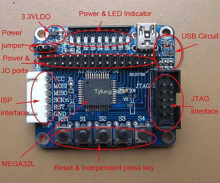
When I was looking at products to buy I saw this little board which is commonly referred to along the lines of ATMEGA32 Minimum System Board AVR Development Board.
The product looked quite a nice little board for prototyping due to its minimalist approach and size. There are 4 switches and 8 LEDs on board that can be used and all I/O from the ATMega is brought out to a header. Here is the board pictured below
Features:
– MCU is ATMEGA32L
– System clock 16MHz
– Onboard 3.3V LDO, power indicator lamp, 8 LEDs, one Reset button, 4 independant button, reserve asynchronous clock interface, USB power supply interface.
– Pin out all 32 IO port, jumper choose 3.3V/5V voltage, 6 pin ISP download port, JTAG interface
– Could download directly from USB port
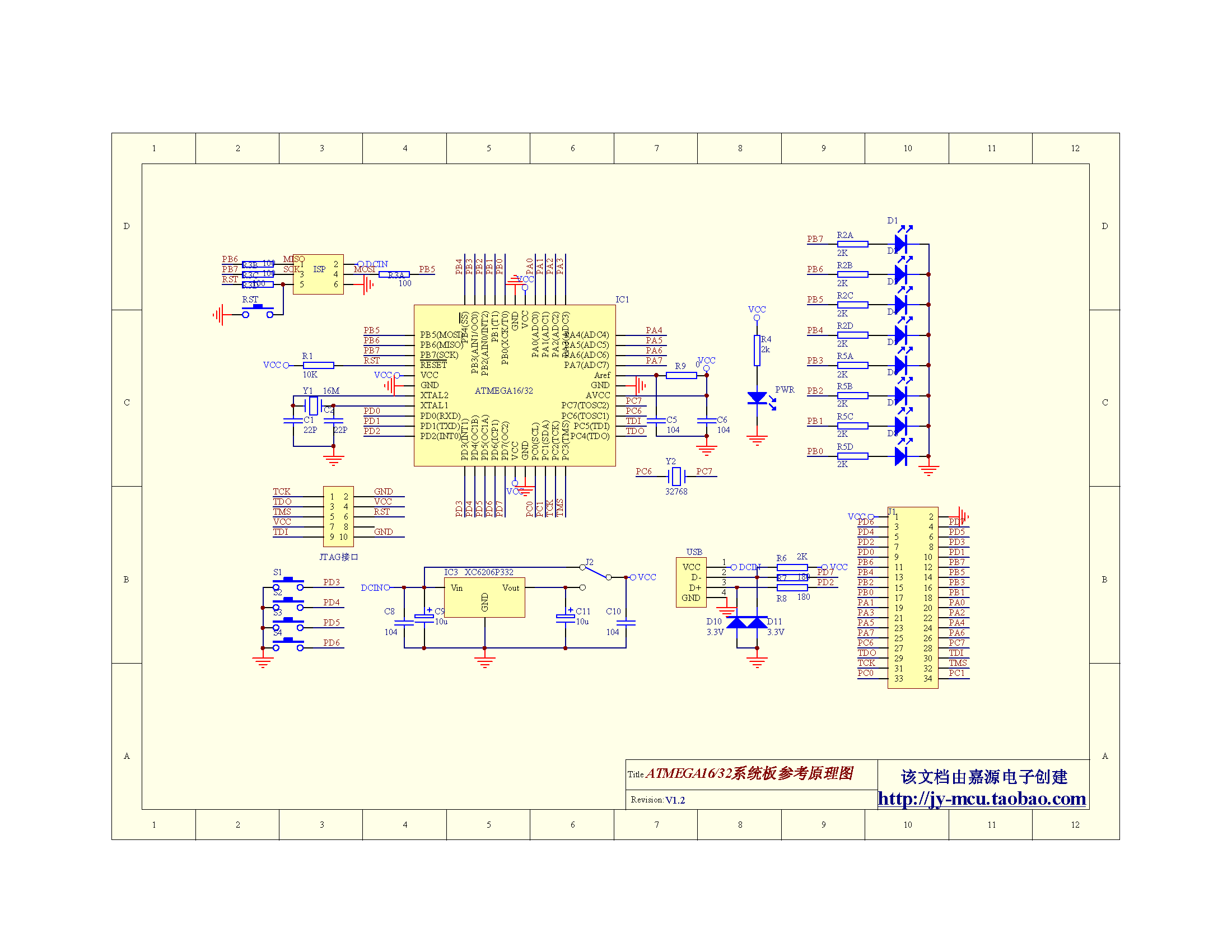
As usual this appears to be a mass produced Chinese developed board with very minimal instructions, now its not the most complex to understand but a schematic is still useful. Anyway I’ve dug up some information. First of all here is the schematic
Looking at the schematics the LEDs are all connected to PORTB, so we will flash these on and off, a sort of hello world type test
Code
This example was written in Atmel Studio
[codesyntax lang=”cpp”]
#ifndef F_CPU
#define F_CPU 1000000UL // 1 MHz clock speed
#endif

#include <avr/io.h>
#include <util/delay.h>

int main(void)
{
	DDRB = 0xFF; //Nakes PORTC as Output
	while(1) //infinite loop
	{
		PORTB = 0xFF; //Turns ON All LEDs
		_delay_ms(1000); //1 second delay
		PORTB= 0x00; //Turns OFF All LEDs
		_delay_ms(1000); //1 second delay
	}
}
[/codesyntax]
I use a USBAsp programmer with this board, it uses the 6 pin pinout. i actually setup Atmel Studio to program the board using USBAsp
Links
These work out about $10 per piece
2PCS LOT ATMEGA32 minimum system board+Free shipping


