2.9K
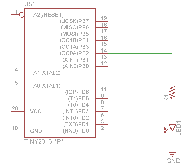
In this example we connect an LED to PB2 (Pin 14) of an Attiny 2313. The PWM output is obtained from the OC0A output of timer/counter0.
Schematic
attiny2313 pwm led
Code
Avr studio code example
[codesyntax lang=”c”]
#define F_CPU 1000000UL
#include <avr/io.h>
#include <util/delay.h>

int main(void)
{
DDRB |= (1 << PB2); // PWM output on PB2
TCCR0A = (1 << COM0A1) | (1 << WGM00); // phase correct PWM mode
OCR0A = 0x10; // initial PWM pulse width

TCCR0B = (1 << CS01); // clock source = CLK/8, start PWM

while(1)
{
// change PWM pulse width every 2 seconds
_delay_ms(2000);
OCR0A = 0x5;
_delay_ms(2000);
OCR0A = 0x10;
_delay_ms(2000);
OCR0A = 0x30;
_delay_ms(2000);
OCR0A = 0x50;
_delay_ms(2000);
OCR0A = 0xA0;
_delay_ms(2000);
OCR0A = 0xFF;
}
}
[/codesyntax]
Links